Partial-Discharge Detection Methods
Overview of partial-discharge detection: Based on the various physical phenomena that occur during partial discharge, two major categories of measurement methods have been developed. 1. Electrical measurement methods: the three methods used in engineering are the radio-influence voltage method (RIV), the pulse-current method (ERA), and the ultra-high-frequency electromagnetic-wave method. 2. Non-electrical measurement methods.
Overview of Partial-Discharge Detection:
Based on the various physical phenomena that occur during partial discharge, two major categories of measurement methods have been developed:
v 1. Electrical measurement methods
The following three electrical measurement methods are used in engineering:
(1) Radio-influence voltage method (RIV);
(2) Pulse-current method (ERA);
(3) Ultra-high-frequency electromagnetic-wave method;
v 2. Non-electrical measurement methods
There are also three non-electrical measurement methods:
(1) Acoustic measurement: measure sound waves or ultrasonic waves;
(2) Optical measurement: measure infrared, ultraviolet, or visible light;
(3) Gas measurement: measure and analyze specific substances in the insulation system.

Components of a Partial-Discharge Measurement System
A partial-discharge measurement system generally consists of four parts: a measuring instrument, a coupling device, a calibration device, and a transmission system (connecting cable or optical fiber).
Propagation and Sampling of Partial-Discharge Signals
Paths through which partial-discharge signals propagate inside a transformer:
① Pulse current (LC transmission circuit)
② High-frequency electromagnetic waves
③ Ultrasonic waves
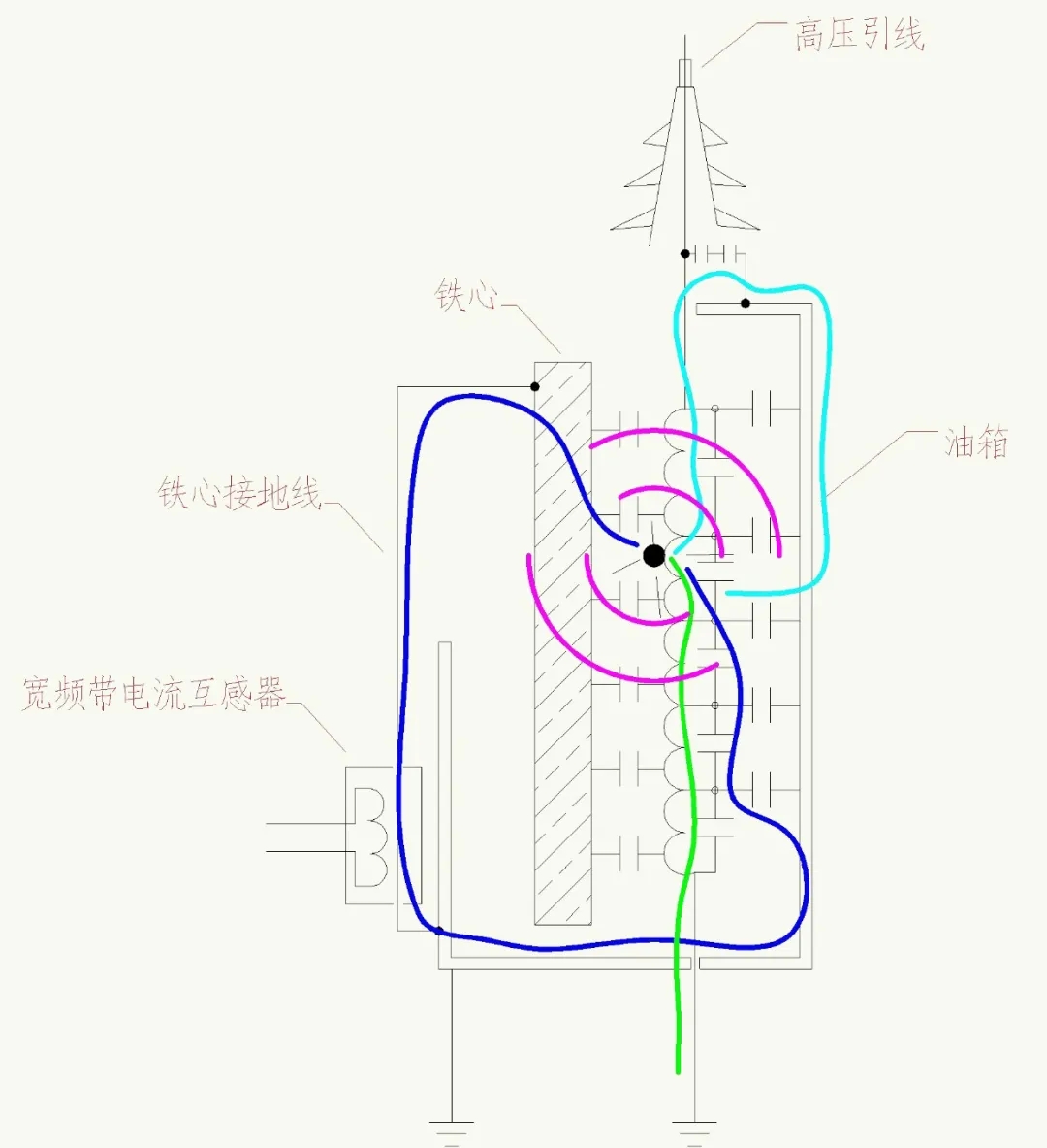
Diagram of partial-discharge signal propagation paths ↑
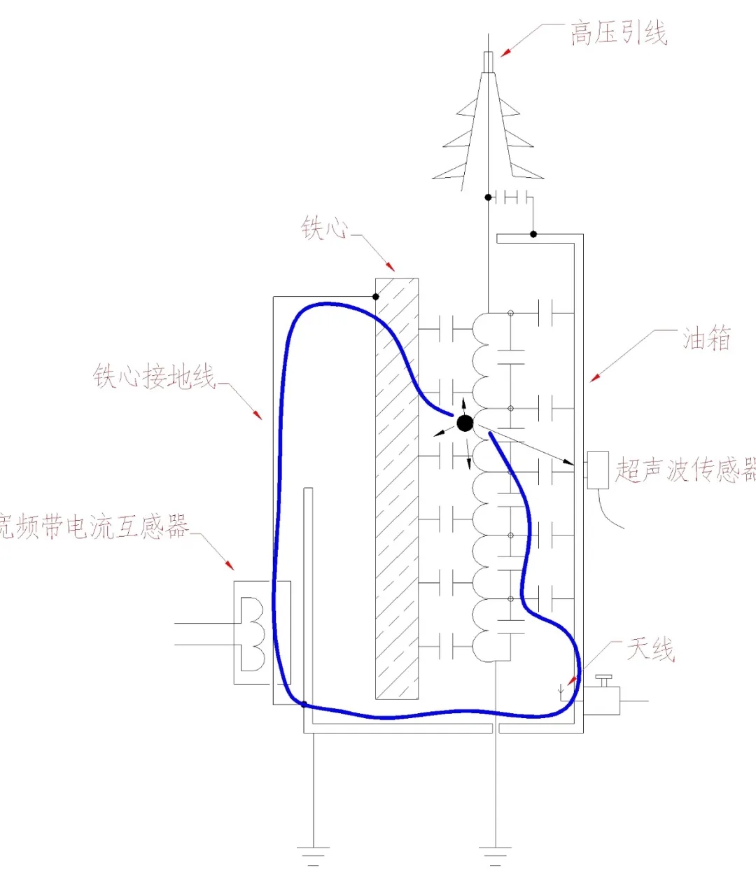
Diagram of partial-discharge signal sampling ↑
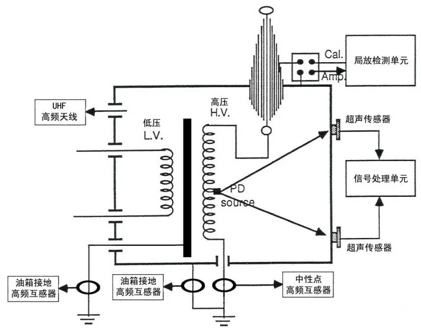
Partial-discharge signal sampling methods:
• Wideband current transformer
• Antenna (ultra-high frequency)
• Ultrasonic sensor
Basic Partial-Discharge Measurement Circuits
Basic circuits for partial-discharge measurement using the pulse-current method (ERA method) are generally divided into two categories: the direct method and the bridge method (balanced method). The direct method further includes parallel and series test circuits.
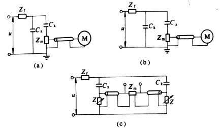
(a) and (b) are direct-method test circuits.
(a) is a parallel test circuit.
(b) is a series test circuit.
(c) is a balanced-method test circuit.
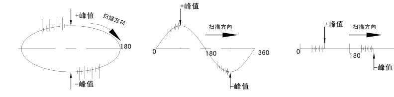
Waveform Display Modes
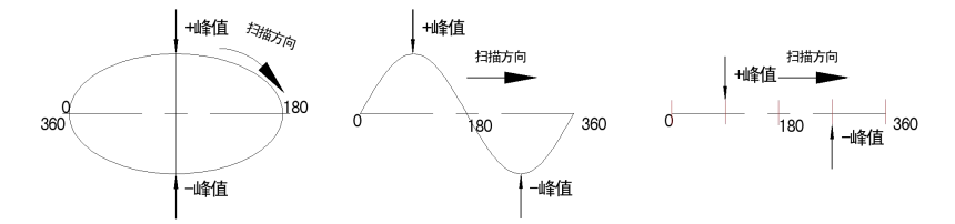
Waveform Display Results
Interference Suppression in Partial-Discharge Test Systems
Interference unrelated to the test voltage (spatial interference):
Suppression methods:
⑴. Use anti-interference measures such as filters, isolation transformers, and wave traps in the test circuit;
⑵. Select an appropriate filter passband;
⑶. Use balanced input;
⑷. Use antenna noise gating.
Interference Suppression in Partial-Discharge Test Systems
Interference generated by the generator and interference caused by the test voltage (power-supply interference):
Suppression methods:
⑴. Increase the diameter of the high-voltage conductor as much as possible (or use corrugated metal hose or a thin copper or aluminum cylinder);
⑵. Add a corona shield to the end of the test object;
⑶. Properly ground all ground wires and metal objects around the test object;
⑷. Do not allow insulating objects around the test object to come into contact with grounded metal wires;
⑸. There must be no metal objects such as screws, nuts, or ground-wire ends on the ground beneath the high-voltage line;
⑹. Use the “antenna noise gating” function to eliminate interference propagated through space;
⑺. Use the “polarity discrimination” function to eliminate interference entering through the power line.
Interference Suppression in Partial-Discharge Test Systems
Interference caused by ground current (ground interference):
Ground-current interference is divided into two types. One is steady ground interference, generally at a low frequency; it can be effectively suppressed using a passband filter and by improving the grounding point. The other is transient interference, which generally appears as random pulses and is unrelated to the test voltage; it is likely to occur when there are multiple grounding points or grounding is incorrect.
Grounding methods for a partial-discharge test system:
a) Series single-point grounding
b) Parallel single-point grounding
c) Multipoint grounding
Suppression methods:
⑴. Use parallel single-point grounding as much as possible;
⑵. Shorten the grounding conductors and reduce their height above the ground;
⑶. Use an isolation transformer to break the ground loop;
⑷. Use an input adapter to isolate the ground loop.
Principles of Interference Suppression
Time-windowing method:
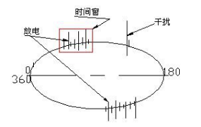
The circuit is opened and closed within a specified time interval to measure the signal during that interval. If interference occurs at regular intervals, the time-window function can be used to place those intervals outside the time window, closing the window to all information outside it.
When AC voltage is used for testing, genuine discharge signals usually recur regularly only within a certain time interval of each cycle of the test voltage.
Antenna noise-gating interference suppression:
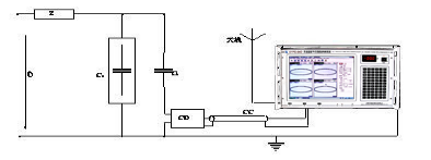
Antenna noise-gating technology generally uses two coupling devices. One coupling device is connected according to the standard wiring arrangement to receive the partial-discharge signal from the test object (including interference signals). The other coupling device is an antenna or antenna amplifier dedicated to receiving spatial interference near the test object. The instrument’s antenna noise-gating function uses the interference pulses received by the antenna to control the “gate” of the channel containing the other coupling device. When no spatial pulse is present, the gate in the signal channel remains open and the discharge signal passes through. As soon as a spatial interference signal arrives, the gate closes immediately, ensuring that the spatial signal is kept out of the channel. All displayed signals are then pulses generated by the test object, without external spatial interference.
Polarity-discrimination interference suppression:
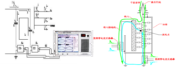
Comparing the pulse polarities at the output terminals of the two coupling devices CD makes it possible to distinguish partial-discharge signals generated by the test object from interference originating in the test circuit. The instrument’s polarity-discrimination function uses interference pulses of the same polarity at one coupling device to control the gate of the channel containing the other coupling device. The channel gate opens when the pulse polarity is correct and closes when the signal-pulse polarity is incorrect. This ensures that all signals displayed in the channel are pulses generated by the test object, without interference from the external test circuit. However, polarity discrimination makes it difficult to distinguish interference caused by electromagnetic induction in the circuit formed by the test object Cx and coupling capacitor Ck from normal partial-discharge pulses generated by the test object, unless another method is used.
Static-interference rejection:
Static interference is interference that appears on the screen at a fixed phase relative to the synchronized voltage of the partial-discharge measuring instrument before voltage is applied to the test object or immediately after the circuit is switched on. It remains fixed at the same point in the voltage waveform. This is called static interference, and the method used to suppress it is called static-interference rejection.
Dynamic-interference rejection:
During partial-discharge measurement, strong random interference often occurs. Its amplitude is large, it is unrelated to the voltage, and its phase is random. This type of interference is called dynamic interference.
Interference at special frequencies:
Intelligent recognition can be used to eliminate radio waves and similar oscillating waves.
Filter passband and digital filtering:
The instrument’s filter passband is generally determined by a combination of a fixed low-pass filter and several fixed high-pass filters. The high-pass filter frequency range is 10kHz-100kHz, and the low-pass filter frequency range is 100kHz-500kHz; digital filters can be combined in any configuration within the above frequency ranges.
Partial-Discharge Measurement and Location Methods
- Electrical location methods
• Multi-terminal measurement location method
• Polarity location method
• Inception-voltage method
• Traveling-wave location method
- Ultrasonic location methods
• Electrical-acoustic location method:
• Minimum time-delay method (V-curve method)
• Triangular electrical-acoustic time-delay location method (spherical-surface location method)
- Combined ultrasonic location method