Partial-Discharge Testing of Instrument Transformers
In our previous issue, we briefly introduced the test standards for partial discharge in instrument transformers. Xinya Classroom | Test Standards for Partial Discharge in Instrument Transformers. In this issue, we discuss how partial-discharge testing is conducted on instrument transformers, as well as partial discharge in current and voltage transformers...
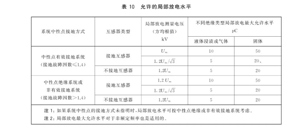
In our previous issue, we briefly introduced the test standards for partial discharge in instrument transformers.
Xinya Classroom | Test Standards for Partial Discharge in Instrument Transformers
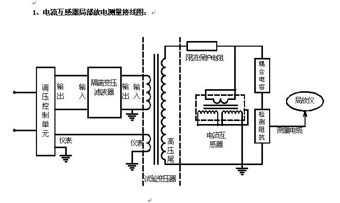
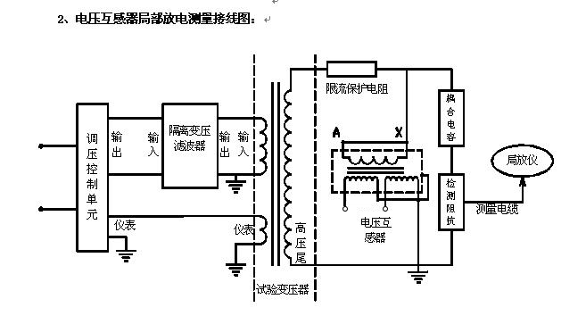
In this issue, we discuss how partial-discharge testing is conducted on instrument transformers, as well as the partial-discharge test circuits for current transformers and voltage transformers.
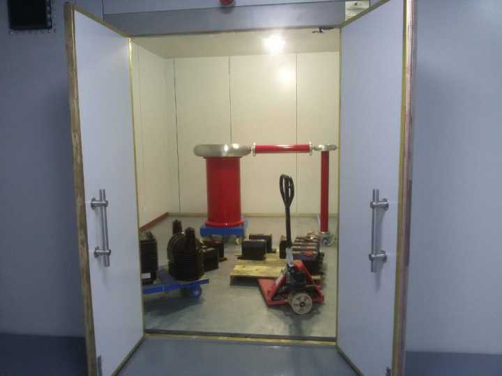
Excessive partial discharge can shorten the service life of electrical equipment. The electrons, ions and thermal effects produced by partial discharge accelerate electrical aging of instrument-transformer insulation and create safety risks. Many instrument-transformer failures in power systems develop as a result of partial discharge. Partial-discharge testing is an effective way to assess the condition of an instrument transformer’s insulation.
When partial discharge occurs in an instrument transformer, a transient voltage is generated across the test object and displayed on the measuring instrument’s peak-voltage meter and waveform screen. Before testing, a calibration pulse is injected to calibrate the test circuit, making it equivalent to the apparent discharge charge, Q0=C0*U0
1
Partial-discharge test circuit for a current transformer
2
Partial-discharge test circuit for a voltage transformer
(Voltage applied to the primary side of the voltage transformer)
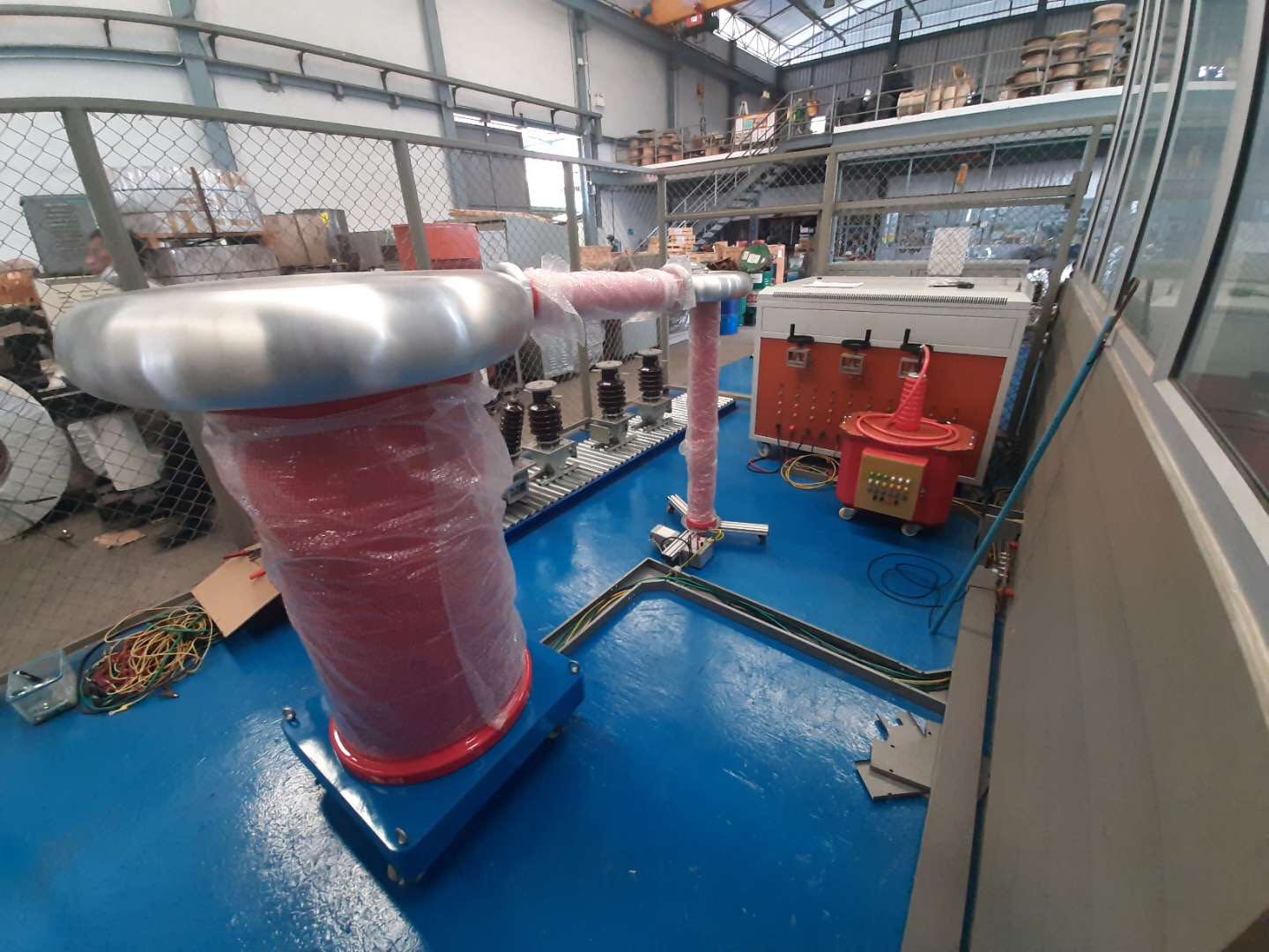
The coupling capacitor used in the test circuits above must not itself produce partial discharge at the test voltage. Its capacitance must also be greater than that of the test object to achieve higher measurement sensitivity. If no such capacitor is available, the inlet capacitance at the test transformer’s high-voltage terminal (the stray capacitance from the high-voltage terminal to ground) may be used instead of a coupling capacitor. In this case, however, do not connect a high-voltage filter, or the discharge pulses will be blocked and the required sensitivity will not be achieved.
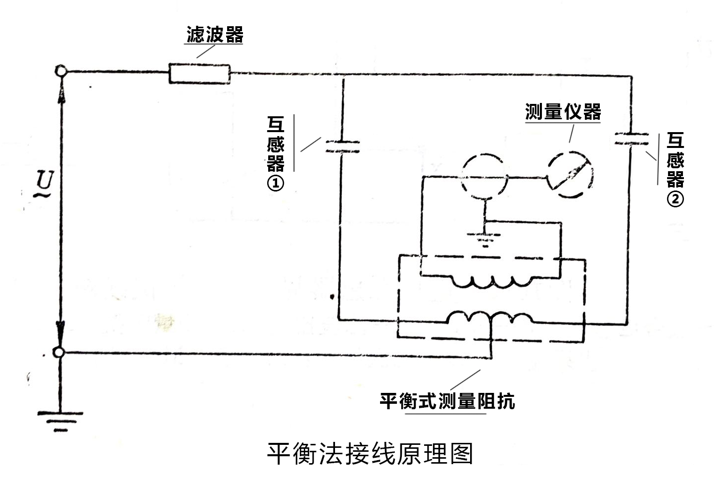
To suppress interference, a balanced-circuit method can be used. With two instrument transformers of the same model and specifications, the best balance can be achieved, and the interference suppression ratio can reach hundreds or even thousands of times. Although a balanced circuit has strong interference resistance, its test sensitivity is relatively low. The balanced-circuit wiring method is shown below.