
Knowledge Boost | Distance Protection Explained in One Article
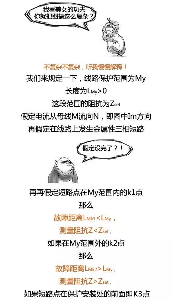
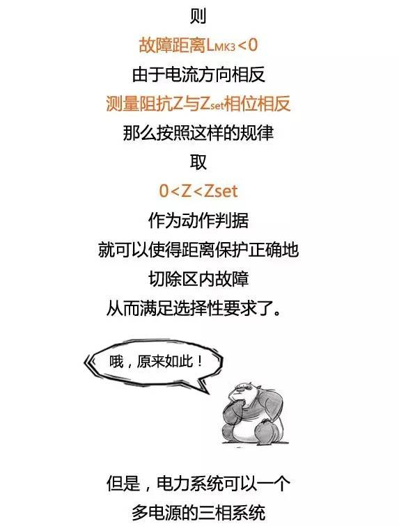
What is distance protection? Simply put, it is a protection device that responds to the distance (or impedance) between a fault point and the location where the protection is installed, and determines its operating time according to that distance. When the short-circuit point is near the protection installation point, the measured impedance is low and the operating time is short; when it is farther away, the measured impedance increases and the operating time becomes longer. This ensures selective isolation of the faulted line.
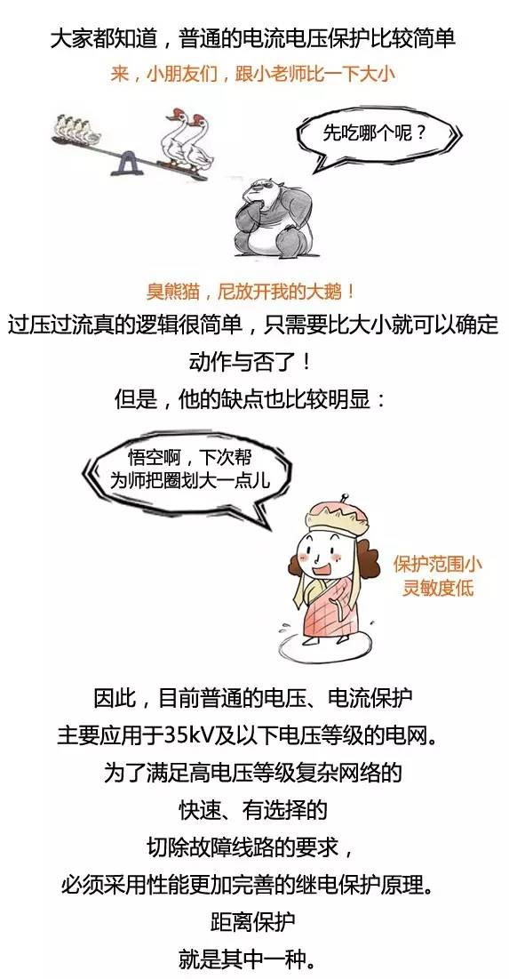

What is distance protection?
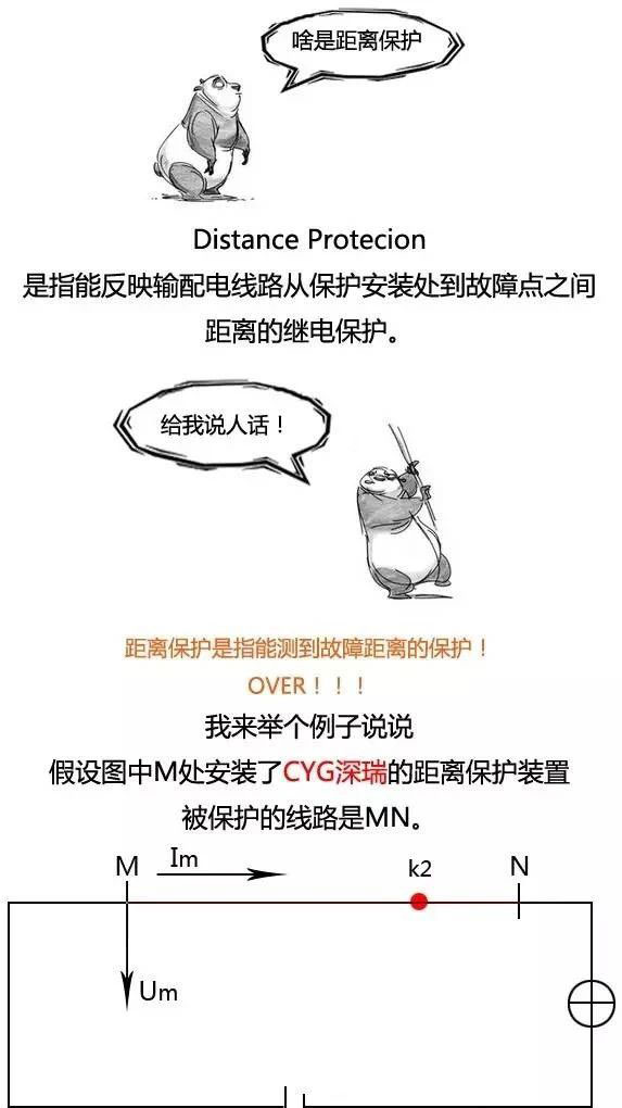
Simply put, distance protection is a protection device that responds to the distance (or impedance) between a fault point and the location where the protection is installed, and determines its operating time according to that distance. When the short-circuit point is near the protection installation point, the measured impedance is low and the operating time is short; when the short-circuit point is farther away, the measured impedance increases and the operating time becomes longer. This ensures that the faulted line is selectively disconnected.
How distance protection works:
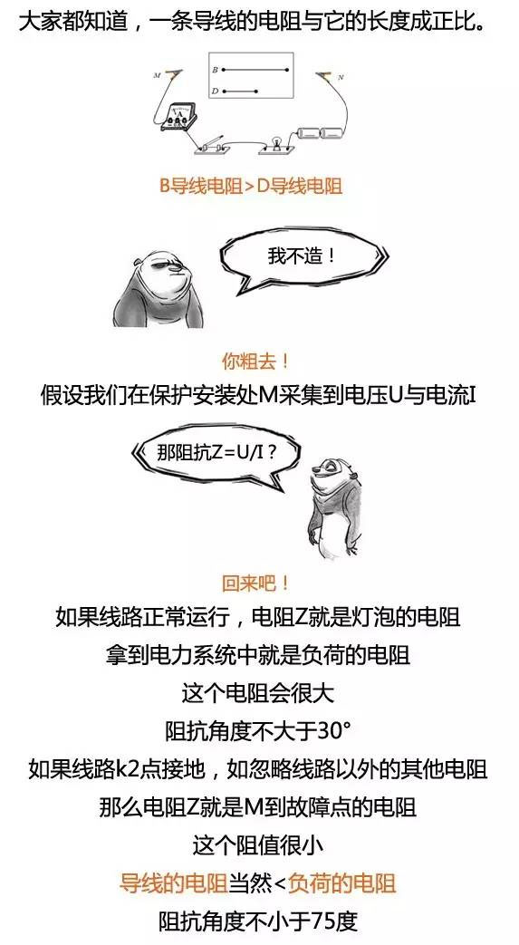
The specific implementation of distance protection is based on measuring the impedance between the short-circuit point and the protection installation point, because line impedance is proportional to line length. As explained earlier, the voltage at the protection installation point equals the voltage at the fault point plus the line voltage drop, i.e. UKM=UK+△U. The line voltage drop △U is not simply the line impedance multiplied by the phase current; rather, it is the sum of the voltage drops due to the positive-, negative-, and zero-sequence currents across the impedance of each sequence, i.e. △U=IK1*X1+ IK2*X2+ IK0*X0 .
Distance protection zones:
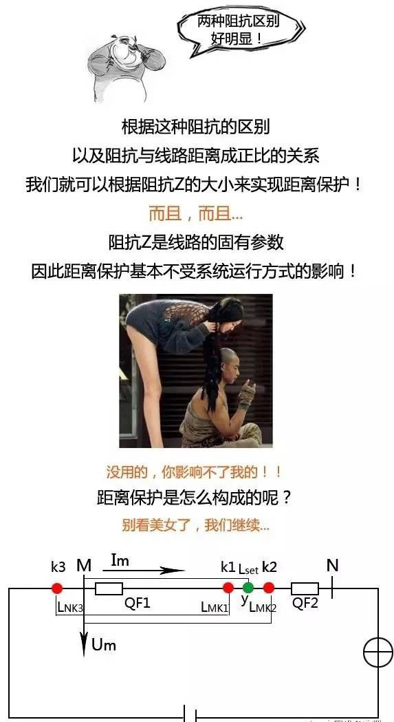
In general, Zone I protects approximately 80%-85% of the full line length and operates without intentional delay. Zone II is coordinated with Zone I or Zone II of the adjacent protection, with an operating delay of 0.5 seconds. Zones I and II together form the main protection. Zone III is set to avoid operation at maximum load current and serves as backup protection; its operating time is coordinated with that of the adjacent line.
Distance protection setting and calculation:
Regardless of the relay used to implement instantaneous current protection, the setting principle is to avoid operation on motor starting current and transient overload. The primary operating-current setting of the relay is generally calculated using the following formula: I = KIS, where: K — reliability coefficient. For the DL type, use 1.4 ~ 1.6; for the GL type, use 1.8 ~ 2.0. IS — motor starting current, generally taken as 5 ~ 7 times the rated current. If the reliability coefficient and starting-current multiplier are not selected appropriately, the relay can easily trip incorrectly or fail to trip. In general, the following principles can be used. Two factors are considered when setting the reliability coefficient. First, consider whether the motor is likely to be overloaded; use a higher value when overload is more likely and a lower value otherwise. Second, consider the electrical distance between the motor and the relay’s current-measuring element.
What components make up distance protection?
Distance protection generally consists of starting, measuring, oscillation blocking, voltage-circuit-break blocking, coordination logic, and output sections.
-
Starting section. The starting section determines whether a fault has occurred in the power system.
-
Measuring section. This is the core of distance protection. Under a system fault, it must quickly and accurately determine the fault direction and distance and compare them with the preset protection zones. It issues a trip signal for an in-zone fault and does not operate for an out-of-zone fault.
-
Oscillation-blocking section. Power-system oscillations are not short circuits, so distance protection should not operate.
-
Voltage-circuit-break section. A break in the voltage circuit causes the measuring supply for the protection to disappear and may cause the distance-protection measuring element to operate incorrectly. In this case, this section should block the protection.
-
Coordination-logic section. This section implements the logical coordination among the components of distance protection and the time coordination among the stages of three-zone distance protection.
-
Output section. The output section includes the trip output and signal output. When the protection operates, it energizes the trip circuit and issues the corresponding signal.